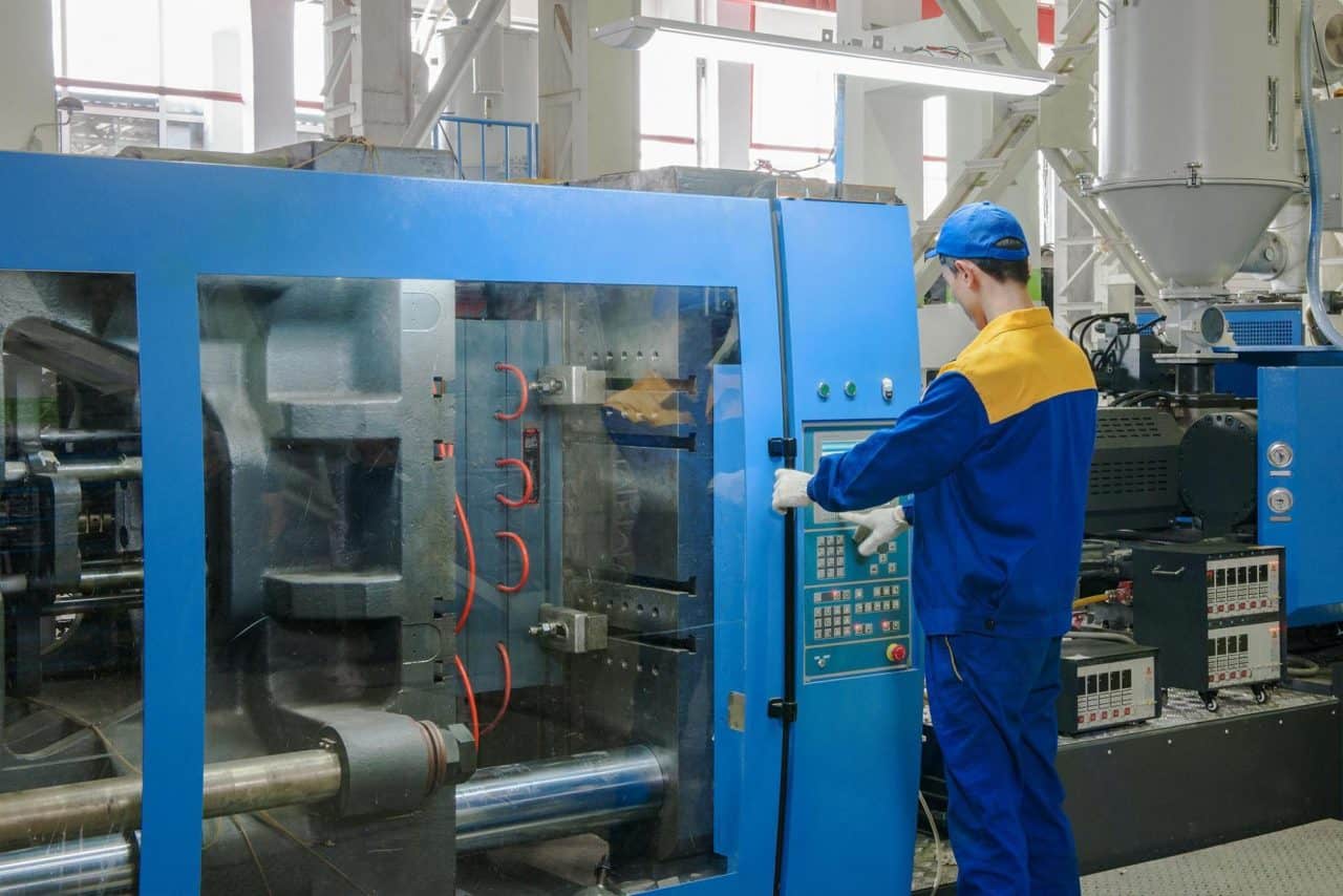
Injection moulding: 5 tips to be flawless

We meet injection-moulded products every day. Smart phones, computers, cars, toys and home appliances would essentially not exist without this technology. Injection moulding is capable of producing objects with complex shape and low geometric tolerance; thanks to this feature, this technology gives the largest amount of polymer products manufactured in plastic processing. Most of the time, injection moulding refers to the injection moulding of plastics, but any powder-based material (most commonly metal or ceramics) mixed with proper adhesive can also be injection moulded in theory. Hereinafter, we only focus on the production of plastics.
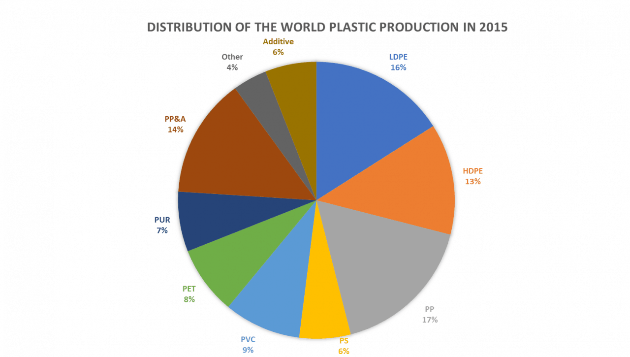
Before addressing the correct way of producing injection-moulded objects, the worldwide popularity of this technology is shown; its great success is attributed to its rapid and automated process and economic manufacturing. Due to the continuous development, the production of plastics almost tripled in the past 3 decades and is twenty times more than was in 1965.
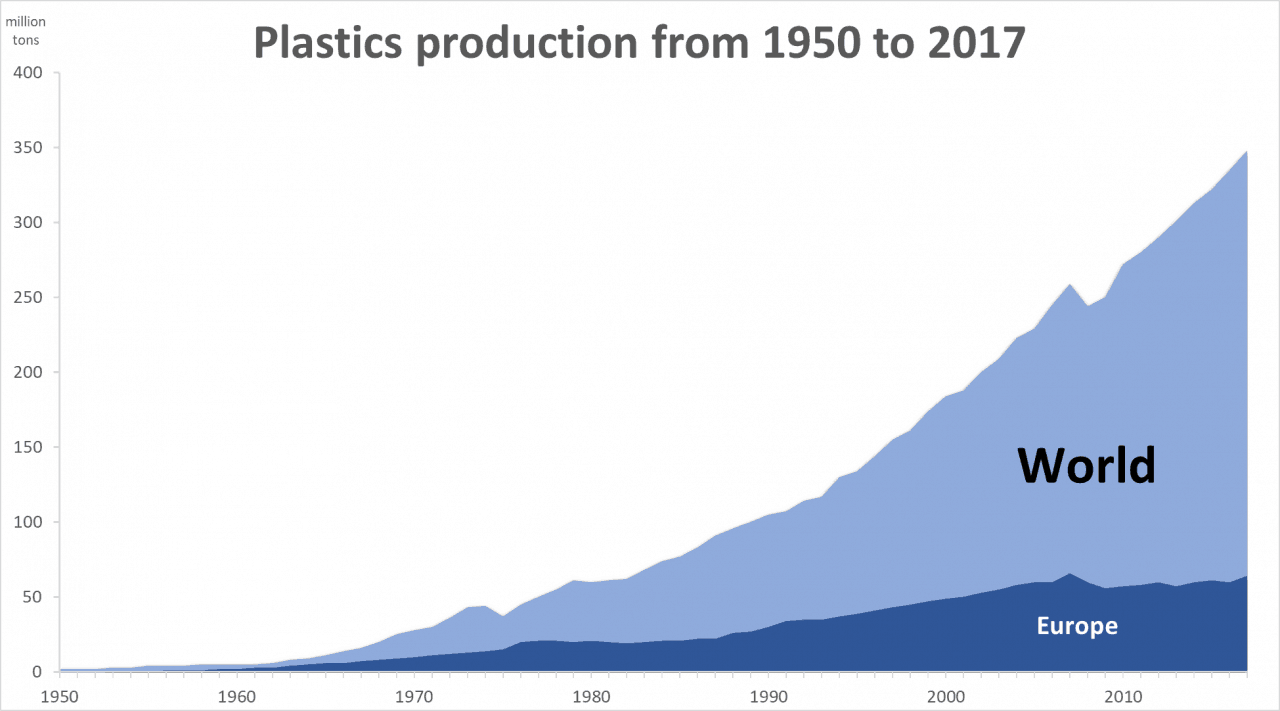
This meant 348 million tons of plastic in 2017, which is a 4% increase compared to the previous year. 64 million tons of plastic was produced in Europe to which Hungary contributed with 1.5 million tons. The financial crisis of 2008 and the subsequent unprecedented rapid growth can be clearly seen in the diagram.
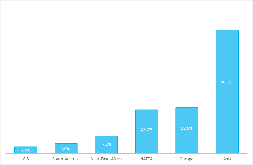
Asia, the king of plastic production

Europe gave 18.5% of the total plastic production in 2017 and is ranked on the second place regarding the total production of the world after Asia, which produces 174 million tons. The third in this ranking is North America, and the remaining 14% is shared by the Middle East, South America and Russia.
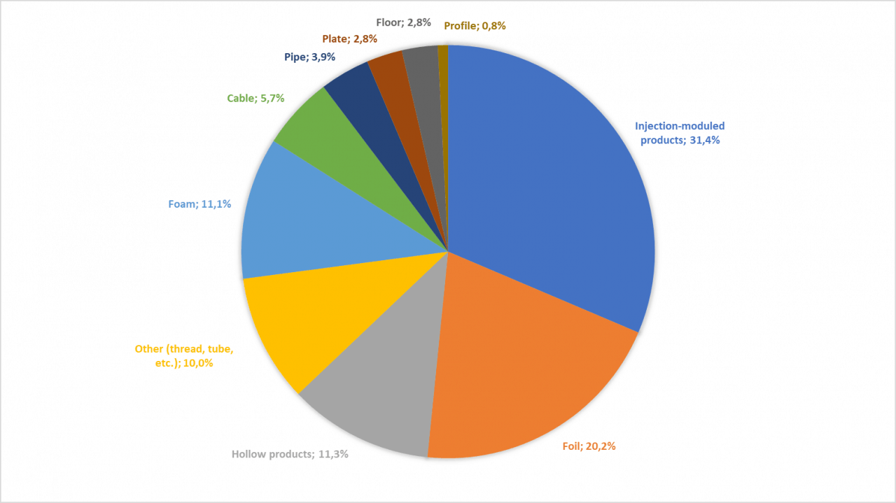
The share of injection-moulded products from total plastic production is variable from region to region, but generally it is above 30% making it the most popular technology for polymer processing. In 2017, almost 32% of the produced 120,000 tons of plastics in Hungary was injection moulded. (Source: polimerek.hu -> Plastic industry of Hungary in 2017)
The most important tips for injection moulding, for 5* design
It is clear that the continuously growing economy has increasing demand for the production and design of plastics (including injection-moulded products). Therefore, we summarized in 5 points what to look out for when designing injection moulding products, what mistakes can be made, and how to avoid producing poor quality or faulty products already during design. However, a well-designed part is not a guarantee for a perfect end product, because countless errors can be made during injection moulding that cannot be controlled by design (e.g. silver streaking, voids, pockets, discoloration, jetting, delamination, burn marks, flash and other deformations). These problems all come from manufacturing technology and can be addressed by changing parameters such as temperature, pressure, time, speed, force or other modification in geometry.
But, let’s see what design engineers can do.
- Selection of proper technology

The design of injection-moulded products begins with the selection of technology after assessing the demands, functions and designs. Besides conventional injection moulding, there are special technologies that require special materials, tools and machines. Without these, the spread of injection moulding technology certainly would have been much smaller. Hereinafter, the most important ones are listed:
- Multi-component injection moulding
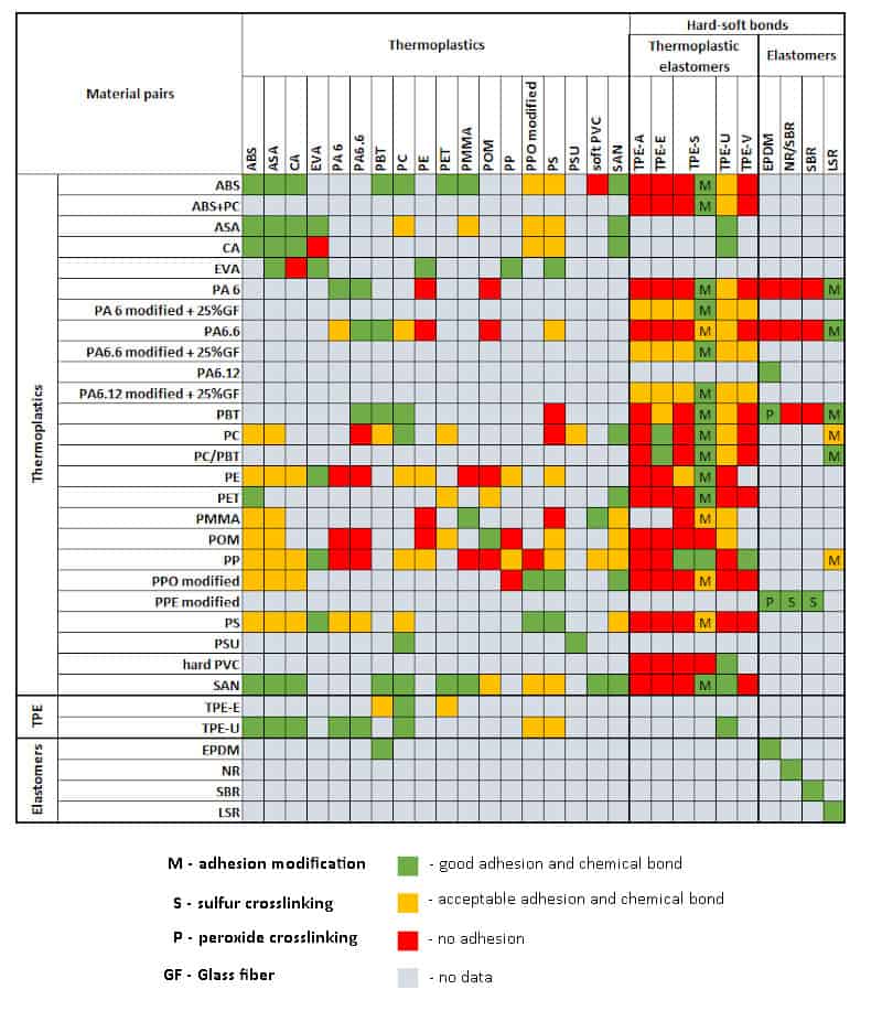
Multi-component injection moulding is the injection of two materials with different types or colours into one plastic part by a machine or a tool in one cycle. Basically, three different processes can be distinguished: bi-injection, co-injection and assembly injection moulding. Bi-injection employs such plastic pairs that can adhere well to each other, and the chemical bond is strong between them. Such a technology is used for producing handles of tools or tail light covers for cars. The co-injection moulding process moulds a plastic part with an outer skin and an inner core. This technology is often used when a strengthened core is needed or from economic reasons. Assembly injection moulding refers to the injection of two poorly adherent plastic parts, which subsequently move, slide or rotate on each other. Using such a technology, plastic chains or pacifiers and their rings can be manufactured without the need of retrofitting. The following table helps to decide which plastics are suitable with one another.
- Gas- and water-assisted injection moulding
Gas- and water-assisted injection moulding is a special type of multi-component injection moulding where the second component is high-purity nitrogen or water, which leaves the mould at the end of the cycle. Such a technology is suitable for manufacturing hollow parts, such as refrigerator handles, armrests of chairs, long/complex pipelines, tv back covers, special bottles, automotive products, etc. The fundamental difference between gas- and water-assisted technology is that gases are compressible, but water is not. Therefore, pressure generated by water remains constant and due to its good thermal conductivity, cycle time is decreased, however a great drawback is its corrosive effect. - Foam injection moulding
The inner structure of products manufactured by this technology is porous, hence foam injection moulding is used for products for which thermal and acoustic conductivity is important. Due to their foam structure, they are lighter, thus they are well-suited for areas where this in important aspect, such as automotive industry. Surface quality is generally poor therefore it can only be used as a stand-alone technology in hidden or aesthetically less important areas. - Injection moulding of inserts
Injection moulding of inserts is a special form of injection moulding, where the plastic is typically injected on the surface of metal inserts. This is needed to ensure electric conductivity, or when the part needs to be strengthened significantly. - Injection on foil or textile
Injection moulding on textile has become prevalent instead of follow-up surface treatment of plastics, and it is commonly used for smart phones, food packaging or car interiors. Such a way e.g. laser engraving, sticking of printed foils and/or lacquering can be done in the same step as the injection itself, thus considerable amount of time and cost can be saved
Injection moulding is an extremely diverse technology and the selection of the right procedure is essential to achieve the perfect end result.
- How to choose the perfect material
The enormous supply of raw materials makes it increasingly difficult to navigate the world of plastics, and a designer should consider many aspects to choose the right plastic material. Therefore, all requirements for the material must be clearly and unambiguously set before commencing the design. This includes colour, opacity, stiffness, strength, durability, life time, UV, heat and chemical resistance, physiological requirements, wear and sliding properties, water absorption, ageing, creep and other aesthetical properties, raw material and production costs, and environmental load, recyclability and the associated biological footprint are also playing an increasingly important role.
Expert knowledge of the entire supply of raw materials is almost impossible, however knowledge of the basic properties of the most important plastics is essential for a design engineer, therefore some features of the 15 most important plastics are summarized below:
|
Material |
Area of use |
Properties |
Density [g/cm3] |
Shrinkage |
Tensile strength* |
Bending resistance* |
|
ABS |
– Medical devices |
– Very good chemical resistance |
1.12 |
0.6 |
41 |
69 |
|
Acrylonitrile butadiene styrene |
||||||
|
HDPE |
– Food and beverage packaging |
– Light |
0.94 |
2 |
26 |
29 |
|
High-density polyethylene |
||||||
|
LDPE |
– Food and beverage packaging |
– Light |
0.92 |
2 |
11 |
11 |
|
Low-density polyethylene |
||||||
|
PA6 |
– Bearings |
– Hard, stiff |
1.13 |
1.3 |
64 |
78 |
|
Polyamide 6 |
||||||
|
PP |
– Household items |
– Hard |
0.91 |
1.5 |
32 |
45 |
|
Polypropylene |
||||||
|
PC |
– Household items |
– Water-clear |
1.2 |
0.7 |
63 |
91 |
|
Polycarbonate |
||||||
|
TPE-E |
– Medical devices |
– Extremely elastic |
1.2 |
1.2 |
25 |
20 |
|
Thermoplastic elastomer – polyester |
||||||
|
PET |
– Bottles |
– Highly shockproof |
1.35 |
1.6 |
64 |
83 |
|
Polyethylene terephthalate |
||||||
|
PVC |
– Water and sewerage system |
– Hard, stiff |
0.6 |
1.4 |
14 |
74 |
|
Polyvinyl chloride |
||||||
|
POM |
– Gears |
– Hard, stiff |
1.42 |
1.8 |
62 |
86 |
|
Polyacetal |
||||||
|
Acrylic |
– Screens |
– Hard, stiff – Highly adhesive |
1.17 |
0.4 |
61 |
103 |
|
Acrylic |
||||||
|
PBT |
– Electronic components |
– Hard, stiff |
1.3 |
1.7 |
53 |
82 |
|
Polybutylene terephthalate |
||||||
|
TPU-E |
– Automotive parts |
– Good abrasion resistance |
1.21 |
0.8 |
14 |
24 |
|
Thermoplastic polyurethane – polyester |
||||||
|
PS |
– Components of household items – Automotive parts |
– Hard, stiff |
1.05 |
0.5 |
35 |
72 |
|
Polystyrene |
||||||
|
SAN |
– Components of household items |
– Hard, stiff |
1.08 |
0.6 |
67 |
104 |
|
Styrene-acrylonitrile |
* www.matweb.com average values for tensile and flexural yield strengths. The exact mechanical properties of a given material can be provided by the given manufacturer.
The plastics industry has developed more than 20,000 thermoplastic and more than 5,000 thermoset polymers, therefore, sometimes even an experienced designer has a difficult and time-consuming task in choosing the best material. There is no general rule for choosing materials as the field of application and requirements for the product are extremely diverse, but it is always advisable to select general and typical materials, and only switch to more advanced plastics if the general ones do not fully meet the needs.
As designers, we are usually in contact with the manufacturer, so it is also worth considering that – with some compromise – the chosen material should be compatible with their fleet.
Matching the right technology to the right material – An example to learn from
The example includes a refrigerator handle, which is much thinner on the supporting surface, for functional reasons, than on the grip. Moreover, the grip is long, cylindrical and curved. It is very difficult to produce it in one piece with conventional injection moulding due to the changing wall thickness, and cutting both ends is only possible with expensive, circulating, long and thin mould inserts. In addition, the end pieces should be injection moulded and perfect fitting should also be achieved. Foam injection moulding would be a good alternative, but one of the requirements for the part is the shiny and decorative surface, which provides aesthetic appearance, but foam injection moulding cannot produce such a part.
Foam-structured inner core can be produced with multi-component injection moulding, but there is no need for internal reinforcement or thermal or acoustic insulation, so the material of the core can be saved by using gas-assisted injection.
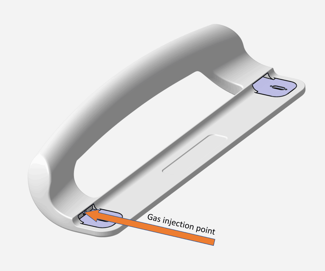
The gas injection point can be concealed on the connection surface, making it invisible during everyday use. Reinforcement was needed around the fixing points, so in addition to gas-assisted injection moulding technology, metal inserts were also placed in two places. The material of the handle is PA6, which is easily accessible in large quantities, extremely tough, abrasion resistant, and also resistant to oils and solvents. It is harmless to health and meets the requirements of the U.S. Food and Drug Administration.
By doing so, the technology and material of the handle meets all the requirements, yet we chose the most cost-effective solution.
- Wall and rib thicknesses are key issues
The process of injection moulding starts with a solid plastic pellet, which is melted and transferred to a mould in which the material takes up the shape of the cavity and then it is cooled back. When designing such a product, it should be borne in mind that certain parameters have significant impact on its quality. One of the most important of these is the wall thicknesses of the product, so we have collected the most important recommendations regarding wall thicknesses for the design of injection-moulded products.
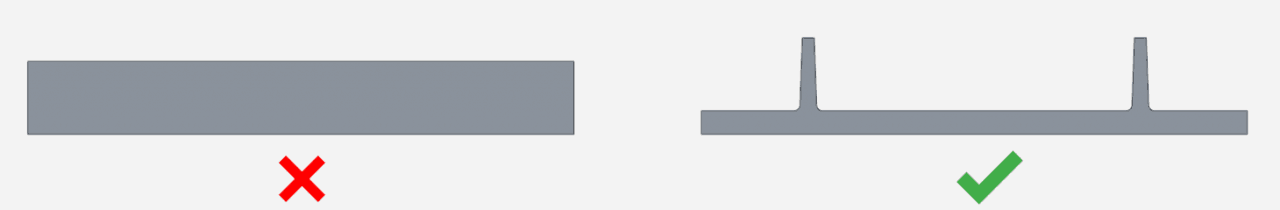
– Thickness of the product should not exceed 5 mm. Very thick parts increase production cycle time and have poorer mechanical properties. A thinner part with ribs is much stronger and more cost-effective.
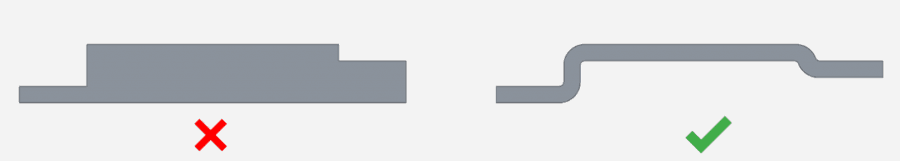
– Always strive to achieve as uniform wall thickness as possible. Sudden changes in material thickness can lead to uneven flow and flow lines, warping, vacuum voids, air pockets or sink marks. Always provide a transition zone for any material thickness change, but if possible, avoid such solutions and place steps on the product instead of material thickening.

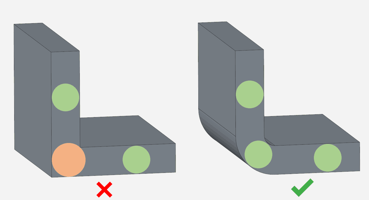
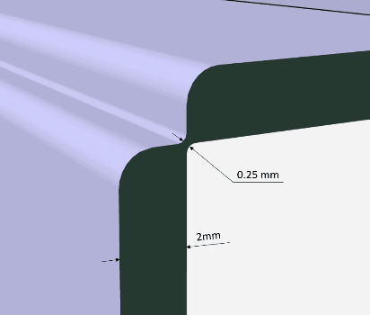
– Avoid sharp corners. Uniform wall thickness cannot be maintained at sharp corners. During modelling, it is always worthwhile to check each cross-section and check the diameter of the inscribed circle as well. This trick can help to be sure that the piece does not contain unnecessary and unwanted thicknesses. In addition, sharp corners concentrate stresses, therefore they should be avoided. It is thanks to this that today aircraft windows are oval, because the world’s first commercial jet airliner, the de Havilland DH 106 Comet, was designed with rectangular windows whose corners suffered fatigue and the planes crashed one year after their launch.
– Do not design large and flat surfaces. Such shapes can curl, warp and deform easily during production; if they cannot be avoided, try to reinforce them with ribs, rounded edges or constantly varying wall thickness.
– Diameter of the inscribed circle increases near ribs. This is unavoidable, but it can be minimized by choosing correct rib thickness.

– Thickness of the ribs is 50-70% of the main element depending on the quality of the material and its shrinkage after injection. For semi-crystalline materials with shrinkage higher than 1.5%, thickness of the ribs is set to 50%, and for amorphous or glass-fibre reinforced plastics with shrinkage below 0.8%, thickness is set to 75% of the main element thickness. In cases where strength requirements would demand the use of thicker ribs, it is more preferred to use two (or more) thinner ribs instead. However, care should be taken to keep adequate distance between the ridges (this will be explained in more detail later). Height of the ribs should preferably not exceed 3 times the thickness of the main element and inclination of the side walls should not be less than 0.5°.

– And finally, as a bit of a curiosity, a widely used solution: the configuration of injection-moulded hinges. This is essentially a controlled plastic deformation. Material thickness is reduced at the given point so that it becomes easy to bend, and the geometry is shaped so that it does not break even after prolonged use. This design is most commonly found in the form of injection-moulded lids for plastic boxes, so that the box itself and the lid are manufactured together in one injection cycle in one mould, which can save production cycle time and the need of a separate tool. The first and most important aspect at the design stage of a hinge is the frequency of use. This considerably influences the material quality and thickness. Regarding the geometry, the following rules are recommended to be followed:
- Design a transition zone between the main element and the gate.
- It is highly recommended to avoid sharp corners.
- Thickness of the gate should be 0.2-0.4 mm.
- The two halves are preferred to be designed in one tooling direction.
- Although it is partly a technological issue, it is recommended to already bear in mind during the design stage that injection of such a part is appropriate if the melt arrives perpendicular to the gate and at approximately the same time at each point.
Complex design? Not a problem! – An interesting example from practice
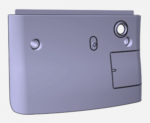
A housing component of a household product should be designed so that after the product has been assembled, it should allow the connection and maintenance of electrical cables through a service outlet. Due to the complicated design shape, it would have been too expensive to manufacture a cover separately, therefore the housing and the outlet cover door were moulded together. The cover door is open in the tooling direction during production and it can be snapped in and screw fastened during assembly.
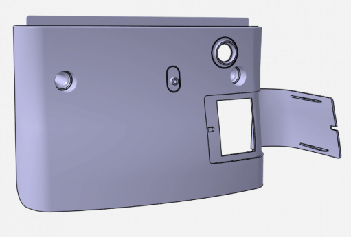
However, this is not the only such solution on the product. For functional reasons, there was a need for such a back-cover design which, in its final form, includes such undercut areas (marked by red dashed line) which makes the product impossible to tool in one piece for manufacturing. All conditions were met, and all requirements allowed to find the ideal angle and fold out this part of the product in ~90° for production. This way, there is no need to manufacture another part separately, and neither tool side has to comprise inserts, making the tool design and manufacturing much cheaper. Prior to assembly, the bottom part only needs to be folded up to return it to its original place.

- Tooling aspects of design
During injection moulding, the plastic melt gets between two tempered mould halves. Here, the material cools, solidifies and then the moving mould plate opens, and the ejector pins extend into the mould cavity pushing the part out. Ideally, a so-called open-close tool is enough, i.e. the piece does not have undercut areas, which could only be tooled with moving inserts. If a product is designed that requires moving inserts, always consider that the inserts need space. Do not design an undercut that cannot be manufactured. The goal should always be to use open-close tool and try to eliminate undercut areas with some tricks, such as using the above-discussed hinges, a cut that can be tooled from the opposite side or simply with the right choice of tooling direction. Tool design and production can also save a lot of time and money later if great care is taken during design.
The ideal tooling direction for even a complicated piece can result in a simple tool.
A swivel chair with complex geometry had to be made suitable for tooling as easy as possible for injection moulding. The tooling direction was selected at an angle of 27.5° relative to the horizontal, and the chair was designed with all its mounting holes and internal cut-outs. This eliminated the need for moving inserts and allowed the entire product to be produced with an open-close tool.
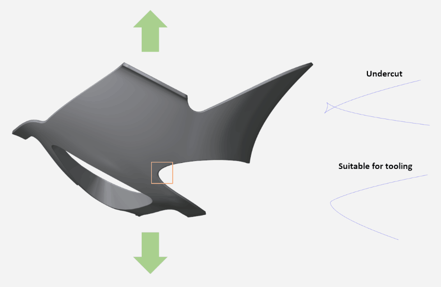
However, the most interesting solution was applied in a very complicated corner of the part. The difficulty was that the dividing surface was placed on a rounded, curved surface in all directions, where the formation of small undercuts depends on slight changes in the geometry. It is very difficult and time-consuming to track its change and formation, so the cross-section of the surface silhouette parallel to the tooling direction was drawn and projected on a plane perpendicular to it, and this projection was examined. A curve intersecting itself indicated the formation of undercut areas, whereas “smooth” curve indicated suitability for tooling.
The tool always leaves marks on the moulded part: ejector pins, injection points, dividing plane between the two sides and moving inserts can leave visible and palpable edges and pointed tips on the surface. These are inevitable features of the technology, but it is an essential need for visible and aesthetic pieces that these should be placed in the most hidden areas, such as on the back or on the edges of the sidewalls. This is also worth paying attention when designing injection-moulded products.
In order for the part to leave the mould without any problem, parallel walls should have adequate inclination (draft angle). Otherwise, the injection-moulded product would get stuck or the tool would scratch or shave the surface of workpiece. A general rule is that all walls in the direction of tooling should have an angle of at least 0.5° per side.
Relatively infrequently, but there are specially designed parts where 0.5° draft angle cannot be maintained due to the special geometry of the surface. But even in this case, as high draft should be strived for as possible. It is recommended to build our models by providing all the walls with the right angle. After the entire geometry has been settled, it is very difficult and time-consuming to make the model suitable for tooling. Almost all CAD software offers draft analysis to keep an eye on the tool to analyse draft angles and detect undercuts. It is worthwhile to check more complex models several times during design.
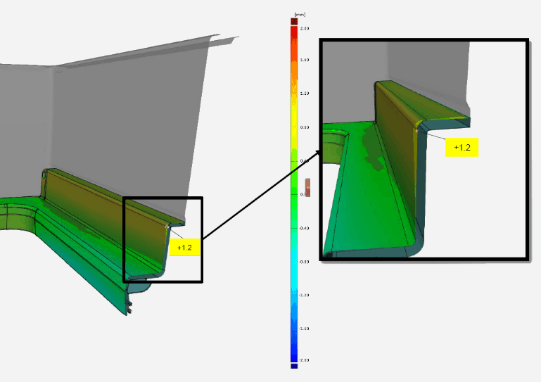
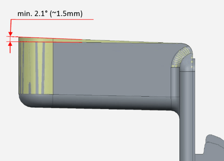
As can be seen in the following example, higher draft angle can also be assigned with a function. A vacuum-formed and an injection-moulded part were fitted with a large gap between them. This was caused, among others, by the inaccuracy of the vacuum forming technology and the shrinkage after injection moulding and the subsequent deformation. The cause of the error was confirmed by optical measurement, alignment and comparison, and a suggestion was made to tilt the mould and so the back side of the product to achieve proper fit.
The production of an injection moulding tool is expensive, so its production is only economical if extremely large number of plastic pieces is planned to be manufactured. During injection moulding, the tool is constantly subjected to thermal and mechanical actions, which continuously reduce the life time of the tool, so always consider the geometry of the tool when designing injection-moulded products. Avoid designs that require long and thin blades or geometric features that are difficult to cool, easily overheated, deform, break or easily damaged during transport. Previously, a discussion was made about the correct height of ribs (which is about 3 times the thickness of the main wall), and here it is worth mentioning how to select proper pitch (the distance between two crests). A general rule is that the distance between the crests should not be less than the height of the ribs. Proper geometry of other grooves and holes are also checked by their height and width ratio (L/d). Avoid designing a geometry that has an L/d ratio higher than 3.
- The key to success is the right joint – What you need to know about the most important plastic joints
A single piece of injection-moulded plastic is often not a final product, but it somehow connects to other parts. Bi-injection, co-injection and assembly injection moulding were previously mentioned as possible ways to join multiple parts or plastics of different colours and materials. In addition to their advantages, however, more expensive special injection moulding machines and tools are needed, and they do not allow assembly with other parts or subsequent disassembly of the products. For this reason, connection of plastics many times should be solved by other ways; in this section, the most important and common plastic joints are summarized.
– Screw fastening:
Screw fastening does not require high-tech equipment, takes up little space, has a large selection, can join plastic parts of different materials and the parts can be easily and relatively quickly disassembled. Its disadvantage is that it can cause tiny cracks, stress concentration, has additional cost and it is not aesthetic.
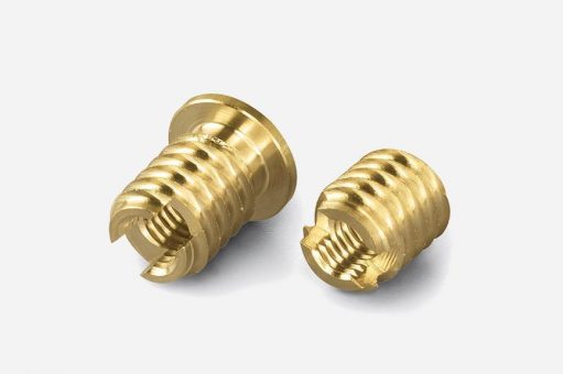
Perhaps the most common solution is fastening with thread cutting screws. It takes up little space, is easy to hide, requires no additional parts or special injection moulding, but has a short life time and can only be assembled and disassembled a few times, so it should be designed in places where the expected number of assembly and disassembly sequences is low. The number of assemblies can be greatly increased by moulded-in or pressed threaded metal inserts and machine screws, which also allow for a much stronger joint. However, they require more assembly time or more expensive injection moulding technology, additional parts and they may lead to the development of internal stresses and the inserts need to be removed before recycling.
Instead of steel, plastic screws and nuts can also be used. These fasteners, of course, have lower strength than metals, but their corrosion resistance and much lighter weight counterbalance their lower strength. Not to mention their lower price and the greater colour choice. The screws loosen over time due to creep and plastic threads may crack or break due to stress relaxation.
Moulded threads as part of the product also allow screw-fastening. The thread geometry can be varied according to individual demands, it provides extremely strong connection and requires no additional parts but has a very expensive manufacturing process due to its slow and specialized production. This approach is generally used for cups, bottles and pipelines.
Pipeline, thread, injection moulding – A real example from the life of CAD-CAM 3000 with a little trick
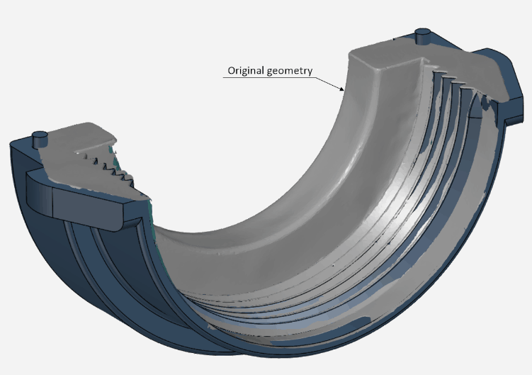
Our client used parts purchased from an external supplier for the connection of pipelines, which included an outside threaded sleeve, a seal and an inside threaded injection-moulded union nut. The union nut was not suitable for connecting pipes or parts with larger outside diameter, and the manufacturer did not have such a nut in sufficient size. To save costs, only the union nut was redesigned.
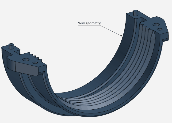
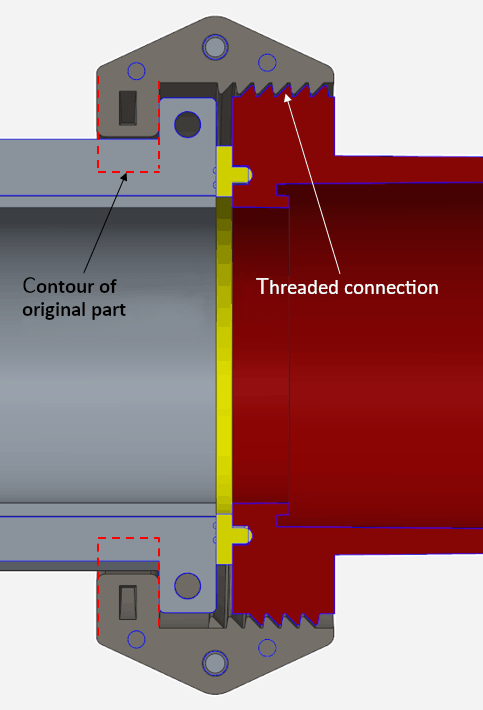
The purpose was to be able to connect a larger diameter component and to be compatible with the threaded design of the original pipe sleeve. In the absence of an accurate model, the original part was digitized with laser-optical measurement, which helped us to easily create the exact geometry of the thread profile and pitch, whereas other parts of the piece were customized to meet the requirements of the client. The nut was designed in two pieces, fitted with alignment pins, and the two halves were fastened to each other with screws. Although two different parts need to be manufactured, it can be installed anywhere and the process of moulding a thread profile had been saved.
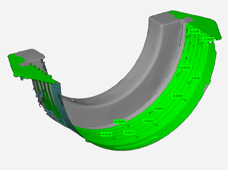
The difference between the geometry of the original and the new part in the thread profile
– Snap-fit joints:
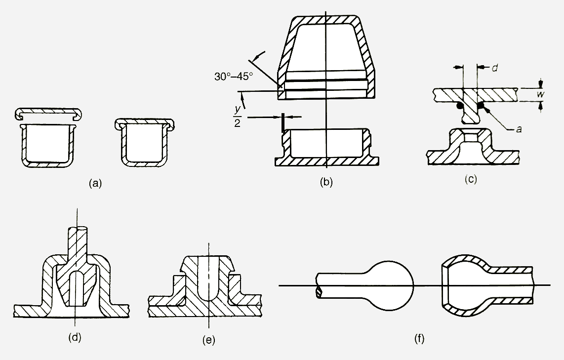
Snap-fit joints don’t require tools, special skills or other fasteners. Plastic parts of various materials can be fastened well to each other; assembly is extremely quick and easy making it the most productive joint type. However, its production is generally more expensive due to undercut areas, snap arms can easily damage during production or transport, and dimensioning is required to ensure proper operation by also considering possible recurring actions. Snap-fit method can create separable joints that can be reopened, or inseparable joints designed in inaccessible locations, which cannot be opened non-destructively. Two basic types can be distinguished: cantilever and annular snap-fits, but a great variety of configurations is possible. Some typical cantilever snap-fits are presented below:

It can be seen that, besides inseparable joints, a wide variety of joints exist that can be disassembled. It is a frequently used solution in household items, plastic toys, automotive industry and for fastening battery covers of remote controllers and electronic devices.
Annular configurations have the same principle of operation as cantilever snap-fits. One of the parts contains a lip or protrusion around the part circumference that engages with a protrusion or a groove on the mating part. The most common annular snap-fits are summarized below:
Of course, there are countless other options besides the outlined solutions, and several other aspects should be considered when determining the correct fastening method.
– Adhesive joints:
Adhesive joining is capable of bonding dissimilar materials, and a well-formed joint provides excellent sealing and uniform stress distribution. Adhesive joints can be hidden very well and are one of the most powerful bonding methods. However, proper joining often requires surface preparation, appropriate environmental conditions or special equipment, all of which add to the total cost, besides the price of the adhesive and all the additional costs related to its use, transport and storage in accordance with the applicable regulations. Moreover, it makes recycling extremely difficult and often involves the release of contaminants, which may require treatment depending on the regulations. Nevertheless, it is still a highly effective weapon in the hands of designers despite its many drawbacks, because it is often the most optimal or the only choice for creating bonding. As designers, we have two tasks when designing adhesive joints: choosing the right adhesive and designing the geometry needed for the joint.
1. There are several things that influence the choice of the right adhesive. The first and most important is the type of the adherends. Not all adhesives are suitable for joining any plastic (let alone joining plastic and glass, leather, fabric or metal). The curing time of the adhesive is extremely important for productivity and the mechanical properties and binding force of the material for its strength. Possible combinations of dissimilar plastics and plastics and other materials would lead to a huge and complex table; therefore, this article does not go into detail regarding these combinations. For the correct selection of suitable adhesives and plastics and other material pairs, the book of Plastics Materials and Processes authored by Goodman, S.H. and Schwartz, S.S., and the tables of 7-4a, 7-4b, 7-4c, 7-4d, and 7.5 of Joining of Plastics by Jordan Rotheiser are recommended.
2. The geometry required for bonding depends on the possible bonding type and the direction of the expected load. Typical loads can be shear, tensile or cleavage force.
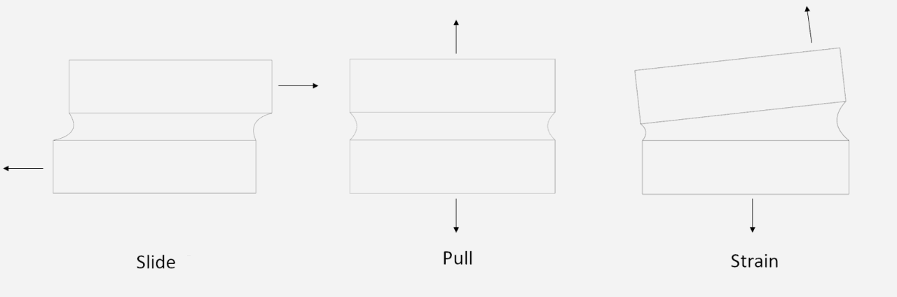
In general, adhesive joints are the most resistant against shear stress, so always try to aim for such a solution. If this is not possible, deign the adhesive joint in the direction of the pulling force and if unavoidable, in the cleavage direction. The adhesive is also an extra material, so when designing joints, the space taken up by the adhesive between the adherents should be considered. A good adhesive joint is active over the entire surface, and the adhesive is only present where the bond needs to be formed, so infiltration of it into areas where it is not needed should be prevented.
Although the topic is more of a machine design, it is worth remembering and keeping in mind during design that gluing can only be done accurately by using machines. Try to help the work of the machine designer by creating well-supported, flat surfaces or tabs / holes on the product that can help effective and quick tooling and gluing.
Adhesive joint “in deep water”
The goal was to create a product that can operate in an aqueous system under constant internal pressure and has moving mechanical parts inside. The housing was formed by joining two injection-moulded halves and, since its water-tightness was extremely important, the adhesive bond was also supplemented with screws.
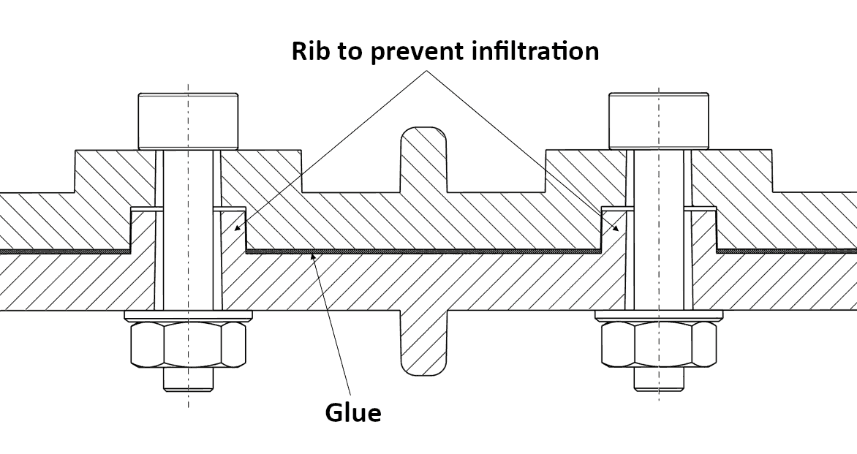

To prevent the adhesive from infiltrating into undesirable places, bosses were designed around the screws and the inner surface of one side was corrugated and grooves and holes were designed on the other side. This made possible to precisely adhere the two pieces together without the need for a device. Joining of two PVC parts can be achieved by a wide variety of adhesives, thus selection of the right material was aided by preparing trial products with different adhesives and load testing them.
Although screwing slows assembly time, the quality of the adhesive joint depends on too many parameters to ensure that it is properly formed, and an accidental leak may turn into a life-threatening error, therefore imperfect sealing or insufficient adhesive strength cannot be allowed. Thus, screws are not only serving to ensure proper adhesion, but they are also load bearing elements.
– Welded joints:
Like metals, plastics can also be welded together. However only thermoplastic materials having the same or nearly the same molecular structure can be attached in this way. As with metals, several types of welding methods have been developed for plastics also, and some of the most important ones are summarized below:
1. Hot gas welding:
Basically, this is the plastic equivalent of arc and consumable electrode welding, except that in this case, the base material and the filler material (which comes through a welding rod or extruder built into a heat gun) are melted with hot air or inert gas. It is a low-cost technology capable of forming large, special-shaped, strong joints, but the process is slow, and the end result is not aesthetic without subsequent surface treatment.
2. Hot plate welding:
The principle of the process is that the two pieces to be joined are pressed to a heated tool and then, the heat source is removed, and the molten surfaces are brought together under pressure. It is a quick and repeatable process; however, it is more expensive, the weld can cause stress concentrations and it is difficult to apply on heat resistant materials.
3. Spin welding:
One of the pieces to be welded is rotated at high speed and pressed against the other. The heat generated by friction melts the plastic and the parts are welded together during cooling while the pressure is maintained. It is a quick and cheap solution, but the parts to be welded must be round.
4. Ultrasonic welding:
In this process, the polymer to be welded dampens the vibrations generated by the ultrasound, damping reduces the vibration energy and thereby producing heat in the material. It is an inexpensive process and can create energy efficient and quick bonding, but continuous weld is not possible to be formed in complicated shapes and large dimensions and not all plastics can be welded well with this technology.
5. Vibration welding:
In vibration welding, the heat produced by friction melts the plastic, but in this case, the heat is generated by reciprocating rather than rotational motion. It is quick and can be used well where spin or ultrasonic welding is not possible. Its disadvantage is that it is an expensive and less accurate technology.
6. Laser welding:
The heat in the polymer is generated by the absorption of a high-energy laser beam. It is extremely precise, has small impact area and high reproducibility, but is very expensive and not all plastics can be welded in this way.
– Rivet joints:
Rivets can join dissimilar plastics to each other and even provide permanent bonding with other types of material. It is a quick and inexpensive solution, but the bonding strength is low, and rivets are not aesthetic. It is a relatively uncommon bonding method and only used in special cases. The following figure shows a few examples of rivets with different geometries:

– Lap joints:
Lap joints don’t require additional materials. It can join different materials, is easy and cheap to assemble, and both inseparable and separable joints can be formed depending on the design. Generally, only cylindrical surfaces can be used for joining, and stress relaxation, creep and thermal expansion of dissimilar materials can cause problems. Higher manufacturing tolerance can only be accommodated more elastic and flexible plastics. The use of lap joints should be avoided when larger loads are expected, it is rather used for separable joints (such as caps or children’s toys).
– Tolerance chain analysis:
Injection-moulded products are also produced with manufacturing inaccuracies. The degree of this depends on the material and size; this information can be received from the manufacturer and the applicable standards. However, when multiple pieces are connected like chains, manufacturing tolerances can add up, making it difficult for the design engineer to determine the correct connecting dimensions and tolerances. RSS or Worst Case calculation methods can help in this, but we do not go into detail in this article.
In addition to our professional experience, we are often inspired by masterpieces of technical literature. If detailed guidance is needed on the design of injection-moulded plastic parts, whether it be precise technological description, detailed material properties, mechanical and other calculations, geometry design or any other topic that is not covered in this article, the following sources are recommended:
– Antal Dunai and Dr. Levente Macskási: Műanyagok fröccsöntése
– Peter Unger: Gastrow Injection Mold
– E. Alfredo Campo: The Complete Part Design Handbook For Injection Molding of Thermoplastics
– Paul A. Tres: Designing Plastic Parts for Assembly
– Jordan Rotheiser: Joining of Plastics
Our article only briefly touches tens of thousands of pages of technical content, descriptions, standards, and recommendations on injection moulding, nevertheless it is clear that success in designing injection-moulded products depends on numerous factors. There are a number of criteria that must be met in the design process, and all of which must be given due consideration. Otherwise, a large number of faulty, non-aesthetic, malfunctioning, unduly expensive parts will be produced. However, by taking our 5 tips and contacting our expert team, you are on the best path to perfect and cost-effective injection moulding.