Automated documentation techniques

One of the main drivers of technological development is to produce a higher quality product in less time; one of the main tools to achieve this goal is automation. Automation is primarily associated with production and manufacturing, however it may also have significant role in reducing the time of the design phase by using automatically generated models and documentation. The main tool for this is the use of macro programs, which do not require programming skills in most CAD software, as almost all software offers the ability to record macros. Anywhere we click, any command we start, anything we type, the program records every moment, and it can be played again any time and even a button or a keyboard shortcut can be assigned to the completed program. This method can save a lot of time, can be used very effectively in simpler cases, but it also contains redundant and unnecessarily repetitive codes in many cases, is only capable of performing very specific operations, not able to set up conditions, execute cyclic commands, interact with users, etc. So, it’s worth learning the language syntax of at least one CAD software with which a lot of time and energy can be saved later. The knowledge of a programming language (most often VBA) is essential for this and useful descriptions can also be found in the help menu of any CAD software. As we equip ourselves with this knowledge, only our imagination sets the limit for implementing any idea; basically anything that the software allows can be done.

We met two major automation needs during our professional activity. One of the main areas of application is to create a product of a given type with arbitrary parameters, or to make it possible. In its simplest case, it is like a toolbox from which screws and nuts of any type and size can be selected and used; this feature is basically already part of all CAD software.
The difference, however, is that we do not work with predefined dimensions and parameters, but provide models with completely user-defined values and properties that can be created from the company’s own products, including custom drawing documentation, automated summary tables, and separate archival titles. The difference, however, is that dimensions and parameters are not predefined, but the model, that can be created from the company’s own products, can be assigned with completely arbitrary, user-defined values and properties. This model may include custom drawing documentation, automated summarizing tables, and separate archivable designations. Let’s see an actual example.
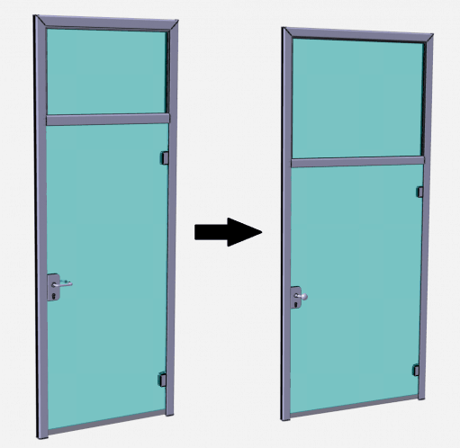
A glass door for a wall system can be ordered and manufactured in any unique size. Door casing profiles include special and size-dependent cut outs; size, weight, and cut outs of the glass are also size-specific, thus unique shop drawings should be made of many parts and the assembly. Of course, the door is only a small part of a complete wall system and is part of a larger assembly, so a customized 3D model is needed.
The dimensions and properties of the door need to be defined in the built-in program, then the program modifies the 3D models, executes the inner and outer renaming and saving based on the project and door code, and updates all related drawings, including custom drawing frames, text boxes, dimensions, weight, date, designer and tables. All necessary parts are prepared in step, and all drawings in pdf and dwg formats. If required, the program also creates a summarizing excel table, including the dimensions of the glass, the total length of required profiles and seals, and a list of fasteners and other standard parts. This means that the complete documentation including 78 files is fully automated with zero possibility of error and it takes only a few minutes to complete it.
The other main application is to produce a large number of similar but different products or product ranges. Creating one at a time would require constant attention and monotonous work, which could easily result in error and can consume a great deal of time and / or enormous human resources. However, with the right automation tools, tens of thousands of file documents for a project can be quickly and easily produced without any error.
In our second example, a complete documentation for a coverage of more than 500 panels had to be created. Each panel is unique in shape, the size, position and shape of their bracing, connections and fittings are constantly changing. A full documentation of a panel comprises more than 15 files, and the total documentation nearly 10,000 files.

Two panels far from each other are very different, but two adjacent panels are very similar. This feature was used in design and a program was written that transfers the parameters of a complete panel and its full 3D and 2D documentation to the adjacent panel. Only a few new references had to be defined, and the program created the new model, updated sheets, cutting contours, hole positions, names clearly defining positions, and saved all files in the appropriate formats. This required not only a suitable program, but also a very complex and well-thought-out modelling, which was extremely attentive to associativity. Thus, the engineering work was minimal, rather narrowed to checking; creation of a panel was 5-10 minutes instead of 5-10 hours and throughout the project, even with the creation of a special program and model, several months of engineering work could be saved.
It is clear from both examples that whatever is the task, automation always aims to radically reduce or minimize design time, engineering interaction, and the possibility of error. It is a tool for engineering problems that, in good hands, represents the pinnacle of automatic modelling and technical documentation.